USTP Ornithopter
The goal here is not merely to build an Radio-Controlled Ornithopter that flies, but to understand why it flies and how to do it in a principled, engineering-driven manner.
1. Introduction
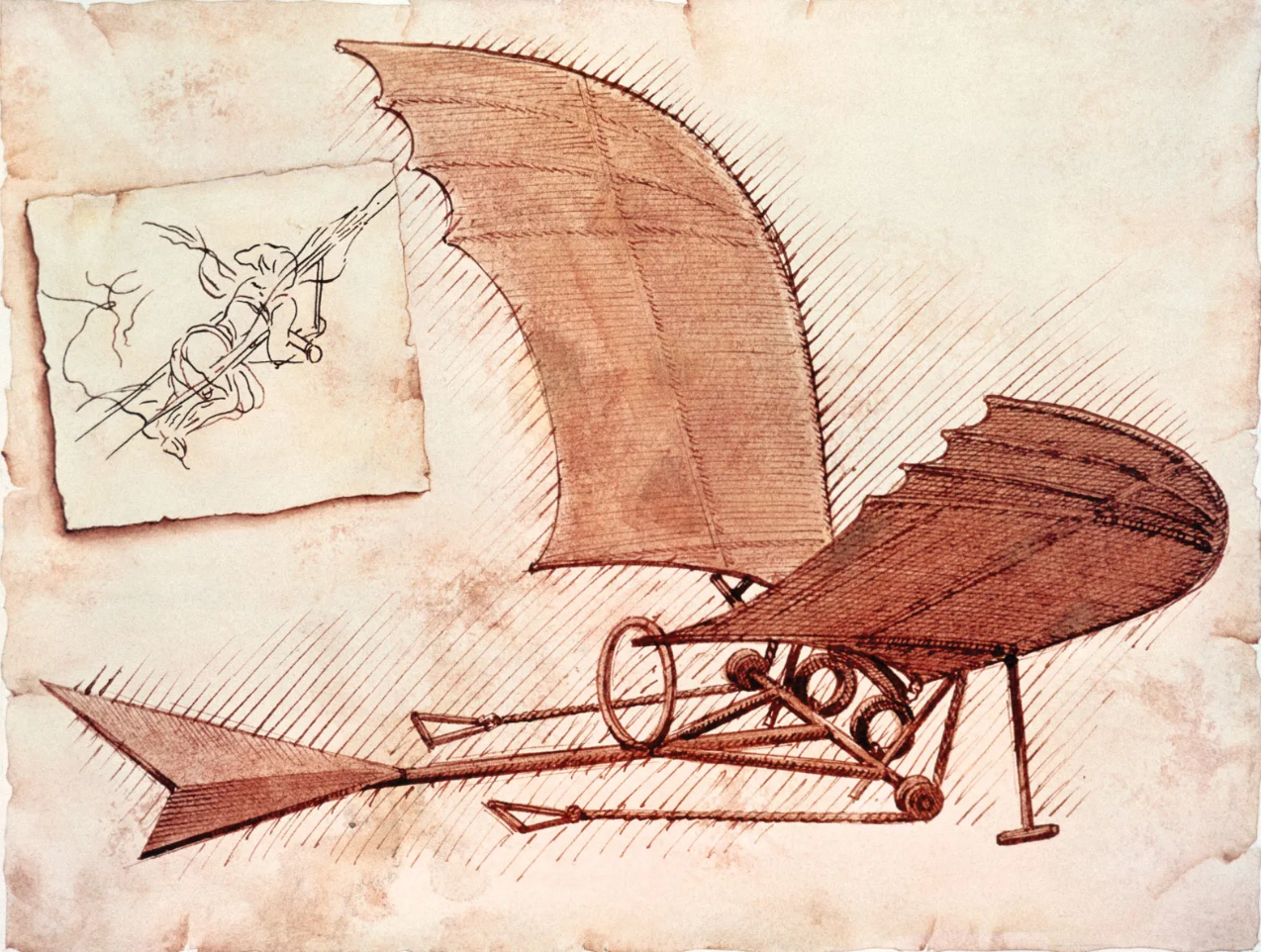
An ornithopter is a flying device that mimics the flight of birds. At face value, the concept is simple; in practice, it is anything but. Unlike fixed-wing aircraft, an ornithopter generates lift and thrust through the periodic flapping of its wings, closely replicating the biomechanics observed in nature. This makes it an ideal engineering problem—deceptively straightforward in description, yet mechanically and analytically complex in execution.
2. Assumptions and Constraints
The first question that must be addressed is fundamental: how do birds actually fly? At its core, bird flight requires two things—lift to overcome gravity and thrust to overcome drag. Birds generate both primarily through the flapping motion of their wings, which are highly specialized, cambered aerodynamic surfaces.
The curved (cambered) shape of a bird’s wing produces a pressure difference between its upper and lower surfaces. As air flows around the wing, the pressure above the wing is lower than the pressure below it, resulting in an upward force—lift. However, lift is not produced by wing shape alone. The flapping motion actively accelerates air downward and backward, and by Newton’s third law, this momentum change produces an upward and forward reaction force on the bird.
In simplified terms:
- Downward force component → lift
- Backward force component → thrust
Flight Regime
- Low-speed, low Reynolds number flight
- Subsonic, Incompressible flow
- Quasi-steady Aerodynamics (unsteady effects are acknowledged but approximated)
- Short endurance flight
- Ground-assisted launch
- Operation in calm air or light wind conditions
- Elastic wing deformation is intentional and aerodynamically beneficial
- All structural components remain within elastic limits
- No plastic deformation under nominal flight loads
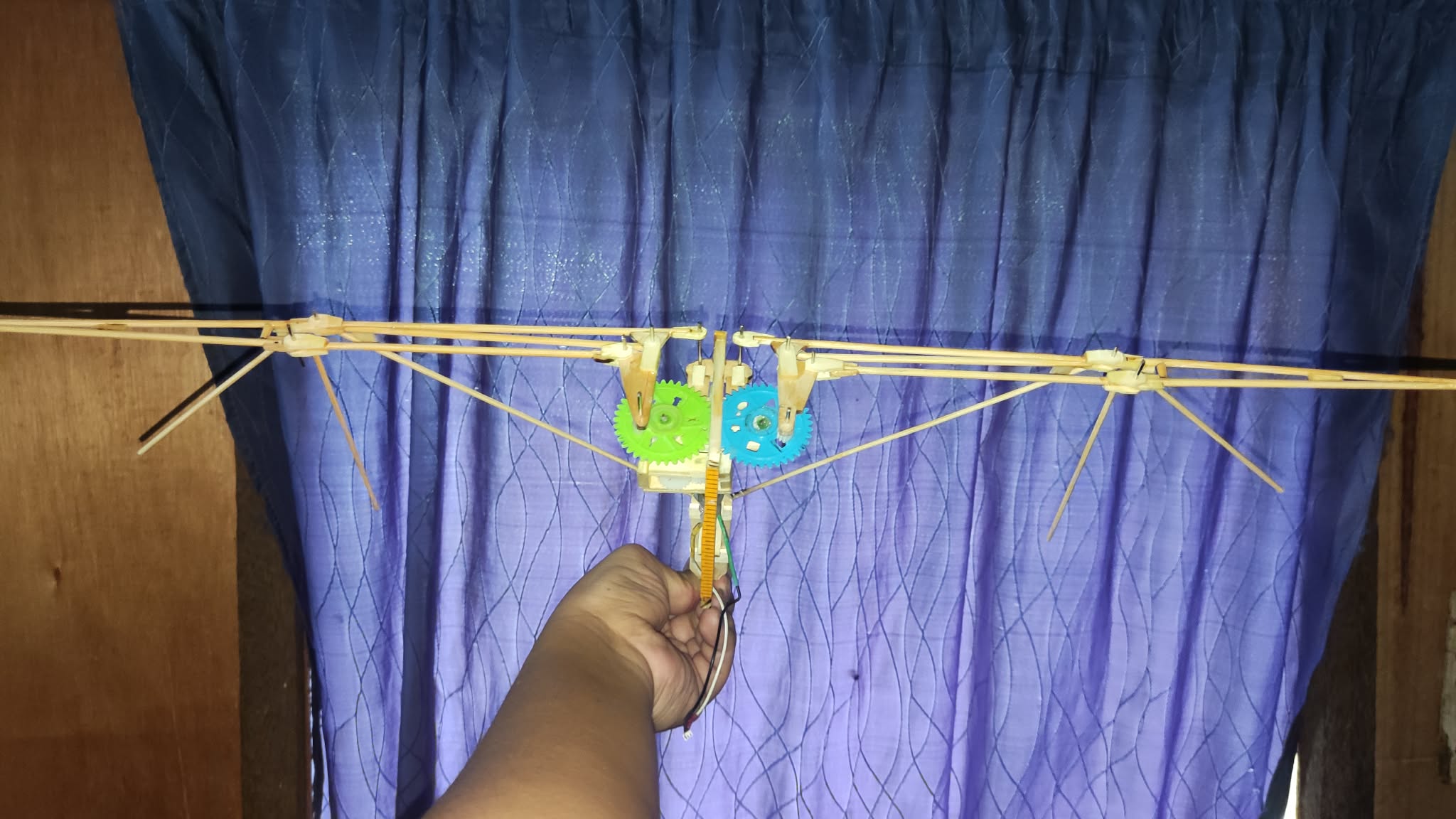
3. The CAD
The flapping mechanism uses a crank-slider driven directly by a coreless motor Wing spars are light wooden material.
4. Analysis and Observations
At peak motor speed, the flapping frequency reached approximately 6 Hz.
Significant torsional oscillation was observed in the wing spars,
indicating under-designed stiffness.
5. Results
- Short hops achieved (< 1 second)
- No sustained flight
- Mechanism reliability acceptable
6. Lessons Learned and Next Steps
Future iterations will prioritize wing torsional stiffness and introduce passive twist via compliant joints rather than rigid spars.