One Ustp bot
This project concerns the design and validation of a reaction-wheel–assisted, wheel-driven inverted pendulum, a classic underactuated nonlinear control system.
1. Introduction
The system consists of a vertical body whose natural equilibrium is unstable, stabilized through the coordinated action of a reaction wheel (to rapidly exchange angular momentum) and a base wheel (to provide forward–backward corrective motion).
Unlike full mobile robots, the system is intentionally constrained to one primary degree of freedom, allowing the project to focus on fundamental control theory, dynamics modeling, and real-time embedded implementation rather than navigation or perception.
Problem Definition and System Goal
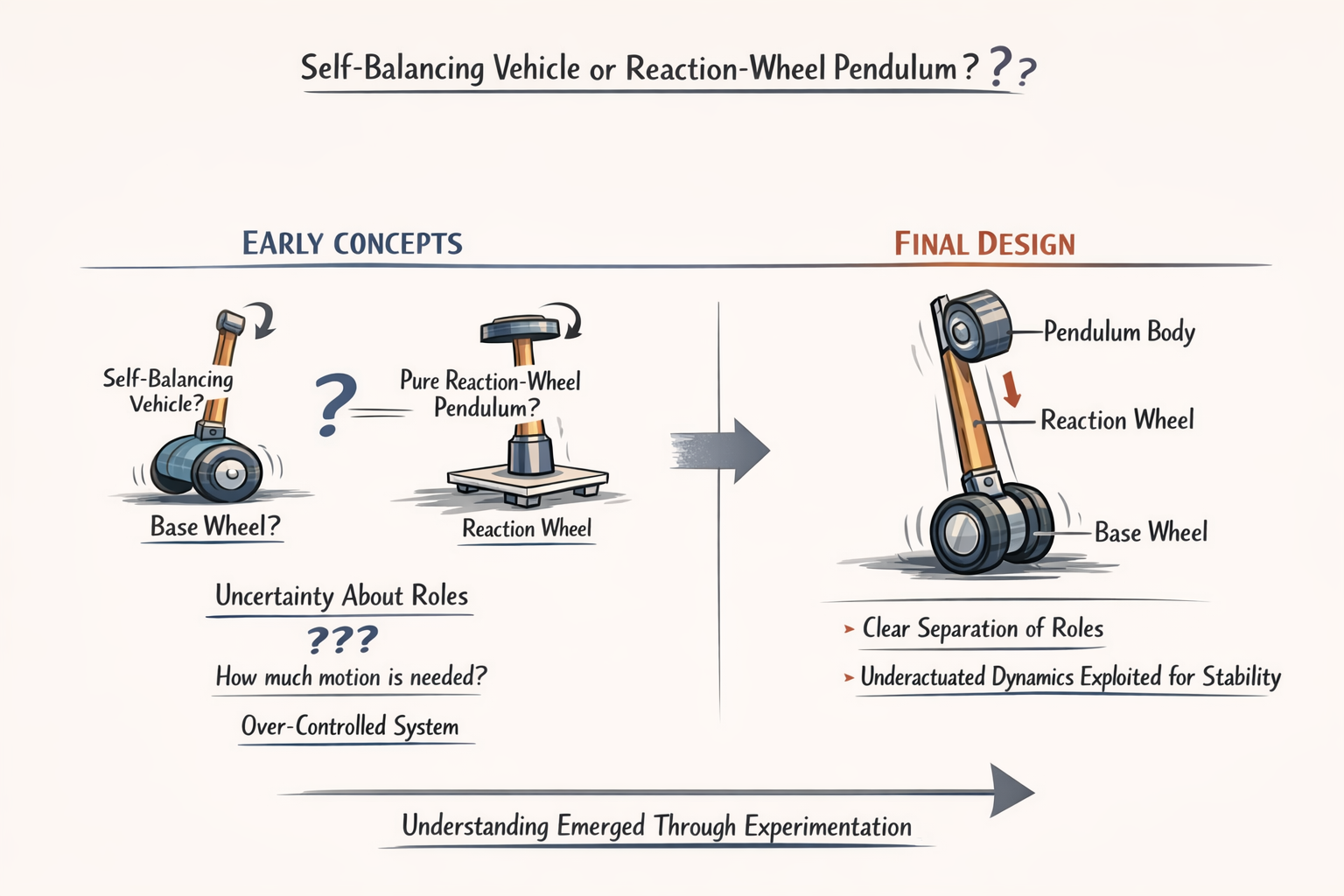
At the outset, the problem was not immediately well-defined as a classical inverted pendulum. Early design exploration involved multiple possible interpretations of the system’s function, including self-balancing vehicles, reaction-wheel–only stabilization mechanisms, and multi-motor balancing platforms. This ambiguity was not accidental but stemmed from the fact that the physical structure appeared to admit multiple actuation and sensing strategies, each suggesting a different control problem. Determining what the system fundamentally was rather than prematurely selecting components became the first and most critical challenge.
Through iterative questioning, comparison with known control archetypes, and elimination of unnecessary degrees of freedom, the system was progressively distilled into its true form: an underactuated inverted pendulum with both reaction-wheel and base-wheel actuation, constrained intentionally to a single balance axis. This clarification step was essential, as attempting to solve the wrong problem formulation would have led to incorrect modeling, inappropriate hardware selection, and unstable control behavior.
Now clearly, the objective should be like this, design a physically realizable inverted pendulum that can:
- Balance upright
- Reject disturbances
- Remain stable using onboard sensing and actuation
- emphasis on correctness over complexity
- Underactuated system
- Embedded microcontroller control (non-industrial use)
System Architecture and Design Trade-off's
After the problem was correctly identified as a single-axis, reaction-wheel–assisted inverted pendulum, the primary challenge shifted from abstract definition to architecting a system that could physically realize the intended dynamics without introducing unnecessary complexity or failure modes.
At this stage, the difficulty was not knowing what components existed, but determining which components were actually justified by the physics of the system.
Multiple candidate architectures were explored implicitly through questions about:
- Motors
- Encoders
- Drivers
- IMUs
- Power Regulation
This led to an iterative refinement process in which components were repeatedly added, questioned, and in some cases discarded. . . not due to lack of availability, but because their role could not be clearly defended within the control framework.
Architecturally, the system converged toward a clear separation of roles: a base wheel responsible for slow, forward–backward translational correction, and a reaction wheel responsible for rapid angular momentum exchange to stabilize the pendulum body. This division was not immediately obvious and required explicit questioning of whether the base wheel should move at all, whether the system was closer to a self-balancing vehicle or a pure reaction-wheel pendulum, and what degree of motion was actually necessary to achieve stability. Only after resolving these questions did it become evident that the system was intentionally underactuated and that stability would emerge from exploiting dynamics rather than directly commanding all states.
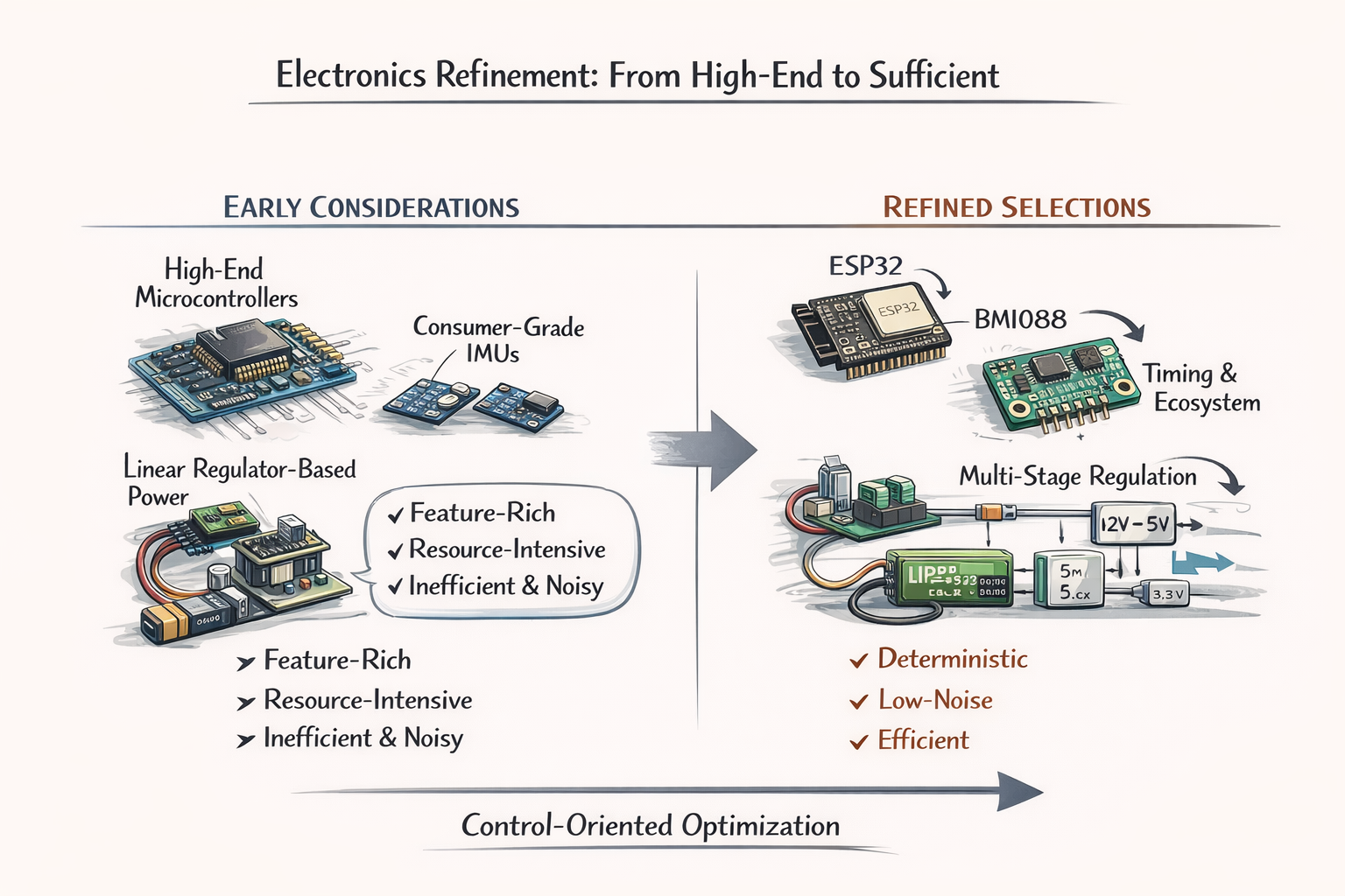
Electronics selection underwent a comparable refinement. Initial consideration of higher-end microcontrollers and more feature-rich IMUs gave way to a focus on determinism, noise performance, and sufficiency. The ESP32 was selected not as a compromise, but because its timing capabilities, processing headroom, and ecosystem aligned with embedded control requirements without introducing the overhead of a full onboard computer. Likewise, the progression from consumer-grade IMUs to the BMI088 reflected a growing awareness that angular rate fidelity, bias stability, and predictable timing mattered more for balance control than integrated filtering or convenience features. Power architecture decisions followed the same logic: linear regulators and single-rail designs were rejected not because they were unusable, but because their inefficiency and noise characteristics conflicted with the realities of a LiPo-powered, motor-driven system. The resulting multi-stage regulation strategy emerged as a necessity rather than an embellishment.
Throughout this process, safety and reliability considerations were not treated as an afterthought but as implicit design constraints that influenced component choice. Concerns about current draw, thermal limits, and failure modes surfaced repeatedly in questions about drivers, regulators, and encoders, ultimately leading to conservative choices and the recognition that features such as physical power disconnects, current awareness, and staged bring-up were essential.
Importantly, these considerations were not imposed externally but arose naturally from grappling with how the system would behave when assumptions failed. . . when motors stalled, when sensors glitched, or when control loops were mis-tuned.
In retrospect, this phase was characterized less by indecision than by progressive constraint satisfaction.
- each question narrowed the design space
- each rejected option clarified the system's true requirements
- each material choice became more defensible as the architecture stabilized
CAD and Simulations
The simulation pipeline was deliberately structured to mirror the physical realities and constraints of the system rather than to maximize software sophistication. Given that the project’s objective is to realize a physically buildable, underactuated reaction-wheel–assisted inverted pendulum, the simulation environment had to satisfy three non-negotiable requirements:
- Correct rigid-body dynamics
- deterministic control-loop interaction
- direct correspondence with embedded implementation
Thus, the selected pipeline will be CAD -> Physics-accurate simulator -> control validation -> optional visualization. . . was chosen because it preserves these requirements in the correct order of dependency.
The process begins with Fusion 360, not because it is visually convenient, but because mass distribution, center-of-mass location, inertia tensor, and mechanical constraints are first-class citizens in a balance problem. Inverted pendulum stability is fundamentally governed by these properties, and any simulation that does not faithfully inherit them risks producing controllers that are mathematically correct but physically invalid. Exporting the mechanical model ensures that the simulator operates on the same geometry and inertia assumptions that will later be realized in hardware, preventing the common failure mode where control laws “work in simulation” but collapse when built.
MuJoCo was selected as the primary physics engine because it is explicitly optimized for underactuated, contact-rich, articulated systems with stiff dynamics, which precisely describes a reaction-wheel pendulum. Unlike general-purpose game engines, MuJoCo solves dynamics using implicit integration and constraint stabilization methods that remain numerically stable under high feedback gains and fast inner loops. This is not an aesthetic preference; it is a requirement. A reaction wheel produces stabilization through rapid angular momentum exchange, which introduces stiff differential equations that simpler physics engines often approximate or damp out. Using MuJoCo avoids tuning controllers around simulation artifacts that would not exist in reality.
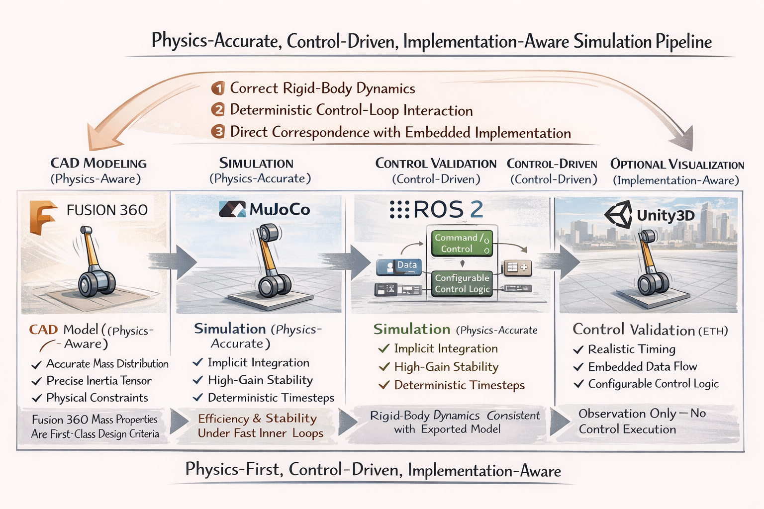
ROS 2 is included only where it provides architectural value, not as a dependency for its own sake. Its role is to structure sensor streams, actuator commands, and state estimation in a way that mirrors the eventual embedded control decomposition. This allows the same conceptual data flow—IMU → estimator → controller → motor command—to be validated under realistic timing assumptions. Importantly, ROS 2 is not used to “control the robot” in simulation, but to verify that the system architecture scales cleanly from simulation to hardware without hidden coupling or timing assumptions. Critics often conflate ROS usage with unnecessary abstraction; here, it is used minimally and deliberately.
Unity3D is positioned at the end of the pipeline and is explicitly not used for dynamics or control validation. Its inclusion is justified solely for visualization, educational communication, and human-in-the-loop inspection. Using Unity earlier in the pipeline would contaminate the control design with non-physical dynamics and frame-dependent artifacts. By relegating it to visualization, the project avoids the common trap of validating stability in a visually convincing but dynamically inaccurate environment. Unity’s role is explanatory, not authoritative.
Alternatives such as Gazebo, NVIDIA Isaac Sim, or O3DE were considered but deprioritized for concrete reasons. Gazebo, while tightly integrated with ROS, relies on physics engines that struggle with stiff, high-gain systems unless heavily tuned, which shifts effort away from control design and toward simulator compensation. Isaac Sim introduces GPU-level complexity, driver dependencies, and an implicit assumption of high-performance computing resources that are fundamentally misaligned with a project constrained to an embedded microcontroller and LiPo power. O3DE, similarly, excels at large-scale simulation and visualization but offers no inherent advantage in accurately modeling the narrow, fast dynamics of a single-axis balance system.
In summary, the simulation pipeline is defensible because it is physics-first, control-driven, and implementation-aware. Each tool is used only where its strengths are essential, and no tool is asked to perform outside its domain of validity. The pipeline does not attempt to impress with breadth; it aims to minimize the gap between mathematical control design, simulated behavior, and real-world execution. Any simpler pipeline would risk invalid assumptions, and any more complex pipeline would introduce dependencies that do not survive contact with embedded hardware.
The Code
The firmware architecture was designed under the explicit assumption that the system is:
- nonlinear
- underactuated
- margin-limited
Thus, the structure is that it catered the common failure modes in embedded balance systems in which:
- it directly mitigates latency coupling
- priority inversion
- control loop instability
State estimation is treated as an explicit computational layer rather than being embedded inside the controller. This separation is critical because it allows estimator validity to be evaluated independently of control performance. In practical terms, this means the system can detect whether instability originates from incorrect state perception or from inappropriate control gains. Many balance projects fail precisely because estimation and control errors are inseparable; this architecture prevents that ambiguity. Furthermore, the estimator operates on physically meaningful state variables that map directly to the equations of motion used in simulation, closing the gap between modeled and real behavior.
The control strategy itself is intentionally hierarchical rather than monolithic, reflecting the physical asymmetry between the actuators. The reaction wheel is assigned responsibility for fast angular stabilization, while the base wheel governs long-term equilibrium and reaction-wheel desaturation. This division prevents actuator conflict and avoids the false assumption that both actuators can or should respond on the same time scale. From a control-theoretic perspective, this reduces cross-coupling and simplifies gain tuning by aligning controller structure with physical causality. Any alternative flat or fully coupled control approach would increase sensitivity to modeling error and reduce robustness.
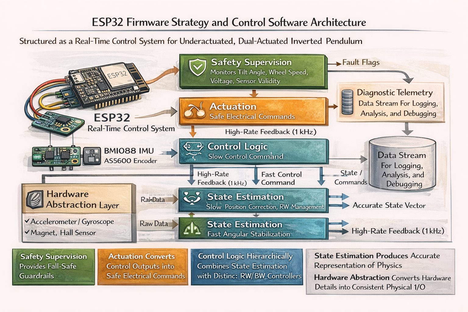
Safety and supervision are not implemented as exception handling but as continuously evaluated control overrides. The firmware assumes that faults will occur. . sensor dropouts, undervoltage events, or saturation and defines deterministic responses for each. This approach avoids undefined behavior and removes the need for operator intervention during failure. Importantly, safety logic is architecturally privileged: it can suppress or override control outputs regardless of software state. This prevents the common failure mode where a “safe” system still executes unsafe commands due to task scheduling or logic ordering.
Finally, telemetry is treated as a controlled, low-priority subsystem that never interferes with real-time execution. All observability is derived from already-computed internal states rather than from additional computation or blocking I/O. This design ensures that diagnostic visibility does not compromise control stability. The explicit alignment between simulation states, firmware states, and logged telemetry eliminates interpretive ambiguity when results are shared publicly or evaluated by third parties.
The ESP32 firmware is structured as a deterministic real-time control system that repeatedly reads sensors → estimates the physical state → computes hierarchical control commands → enforces safety limits → drives the motors, all on fixed timing.
Conclusion